The structural analysis software RFEM 6 is the basis of a modular software system. The main program RFEM 6 is used to define structures, materials, and loads of planar and spatial structural systems consisting of plates, walls, shells, and members. The program also allows you to create combined structures as well as to model solid and contact elements.
RSTAB 9 is a powerful analysis and design software for 3D beam, frame, or truss structure calculations, reflecting the current state of the art and helping structural engineers meet requirements in modern civil engineering.
Do you often spend too long calculating cross-sections? Dlubal Software and the RSECTION stand-alone program facilitate your work by determining section properties of various cross-sections and performing a subsequent stress analysis.
Do you always know where the wind is blowing from? From the direction of innovation, of course! With RWIND 2, you have a program at your side that uses a digital wind tunnel for the numerical simulation of wind flows. The program simulates these flows around any building geometry and determines the wind loads on the surfaces.
Are you looking for an overview of snow load zones, wind zones, and seismic zones? Then you are in the right place. Use the Geo-Zone Tool to determine quickly and efficiently snow loads, wind speeds, and seismic data according to ASCE 7‑16 and other international standards.
Would you like to try out the capabilities of the Dlubal Software programs? You have the opportunity to do so! The free 90-day full version allows you to thoroughly test all our programs.
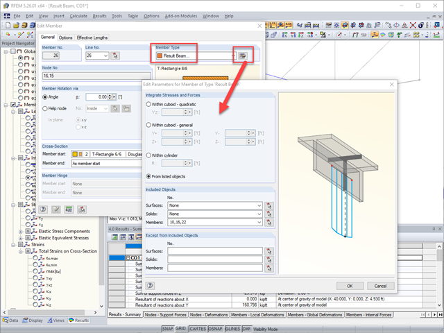
Although member end forces are typically used for connection design (see FAQ 4918 linked below), there may be the scenario that you're interested in the total internal forces at a particular node where several members are framing into this point at various angles. The program does not give internal force result information at nodes by default.
The best option is to create a result beam where you can select which members to consider for the internal force summation. Result beams do not add any stiffness to the model and are used purely as a result interpretation tool (see KB 1406 linked below). You can view internal forces on result beams as you would any other member which the member end force can provide the force summary at a particular node.
Please note, result beams internally create a perpendicular plane at each point along the member length and at both ends to determine which forces shall be integrated in the results. This works well for all elements which do not lie directly in the perpendicular plane to the result beam. For any elements that are directly perpendicular, a very small offset must be applied to the element so it's no longer perfectly perpendicular for the result beam to also capture its results.
Differences in results can also be cause by nonlinear elements introduced in the model. For example, Tension Only members could be deactivated in a LC but activated in a CO because of loading changes. Keep nonlinear elements in mind when adding LCs together in a result combination, as results of failing objects will be set to zero during the super-positioning of the individual load cases. This could lead to unexpected results.
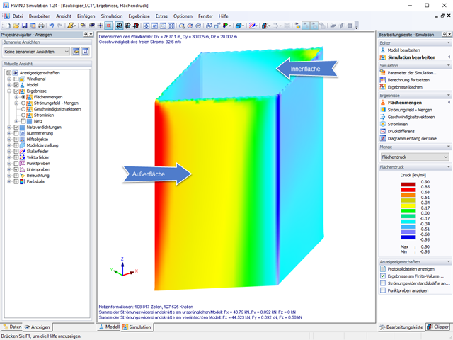
The RWIND Simulation program creates an envelope in the form of a solid mesh around the model from RFEM.
Due to the wind flow around this envelope, a discrete surface pressure distribution arises that alternates between positive and negative values. In RWIND Simulation, this surface pressure is clearly displayed on the outside of the solid envelope.
When transferring data to RFEM, the program transforms these pressures on the outer surface of the solid envelope back to the structural model of RFEM. In this case, the surface pressures are transformed back around
In summary, the internal and external pressures of a structural component to net loads are simplified for the RFEM calculation.
For elements with "double-sided" flow, the surface pressure will always differ between RFEM and RWIND Simulation due to the summation of the surface pressures to resulting pressures.
Furthermore, the orientation of the element coordinate systems must be taken into account when interpreting the wind pressures in RFEM. The displayed pressures do not refer to the sign (positive - pressure, and negative - suction), as in RWIND Simulation, but to the local element coordinate system of the respective elements.